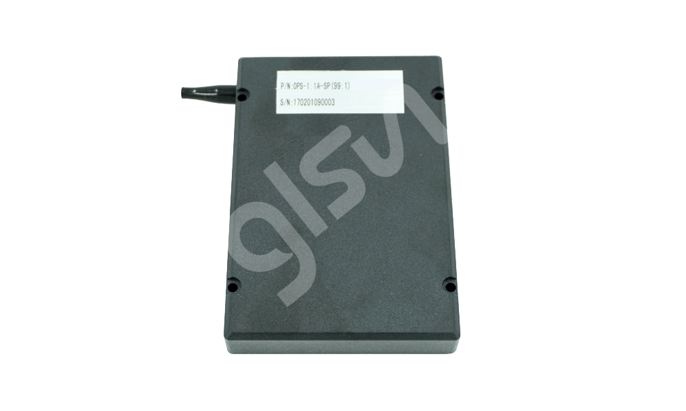
GLSUN Optical line protection (OLP) module is a method of protecting optical fiber communication networks from failures. It works by automatically switching to a backup optical fiber path in the event of a failure on the primary path. This helps to ensure that data can continue to flow even if there is a problem with the primary path.
OLP is a valuable tool for ensuring the reliability of optical fiber communication networks. It can help to prevent network outages, improve network performance, reduce downtime, and improve data loss protection.
Features
·Inputport (IN) light signal output to TXA and TXB via 50/50 splitter.
.Light signal is from RXA to Tap1, 1% for optical power monitoring and 99% for transmission to 1x2 optical switch.
.Light signal is from RXBto Tap2, 1% for optical power monitoring and 99% for transmission to 1x2 optical switch.
.Output port (OUT) will output the light signal from RXA and RXB via selected optical path by 1x2 optical switch.
.The PD monitor results (analog signals) will convert to digital signals by AD convertor and output to management system via I2C interface.
.There are optical switch driving circuitry inside and control the optical switch’s status via electrical pin and timing signals.
.There is EEPROM with I2C interface to keep two demarcated PDs’ linear ranges.
.There is online function inside for status judgment from management system.
.There are 54 optical power data in EEPROM,the optical power of AD monitoring will compare with EEPROM and find the optical power range then upload to management system.
Applications
·Split the input light source to two paths by 1x2 splitter (IN→TXA/TXB).
.Monitoring the optical powers from RXA/RXB and feedback to management system via I2C interface.Management system will control the optical switch via subsidiary circuitries to obtain the optical light path selecting function


