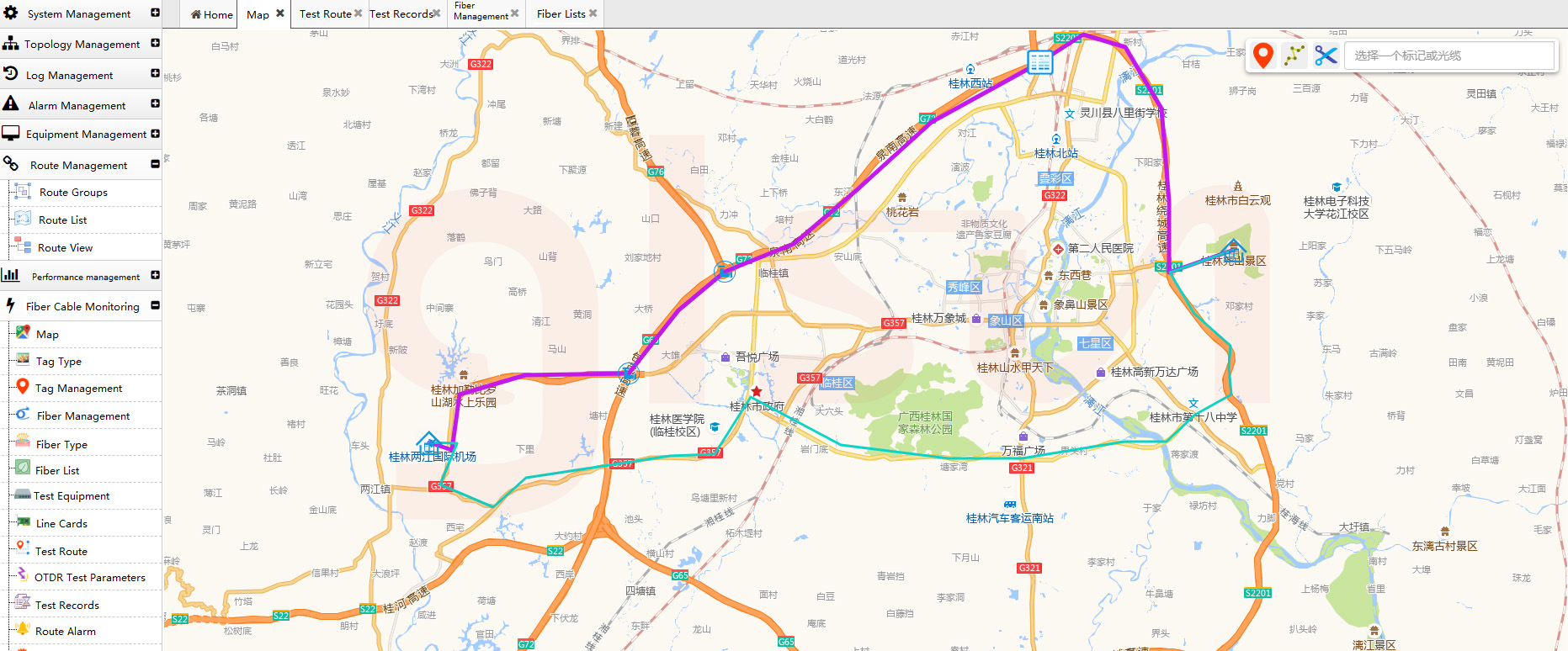
 (NMS manages GIS Map)
In this scheme, the business light and the wavelength1625nm of OTDR are combined to transmit through FWDM through the OUT equipment in one end of the computer room. And then transmit through optical fiber to another computer room.
In the whole scheme, OUT+FWDM+OTDR+OSW+LSU+OPD is used for the fiber optic cable monitoring.
In order to meet the monitoring of 32*2 channel optical cable in real-time, the scheme uses FWDM to combine the wavelength 1625nm of OTDR and the business optical signals to realize multi-link monitoring through OSW in real-time.
Principle
1. Firstly, the output of the OTDR is connected to the COM port of the 64-channel optical switch (OSW).
2. The output port of OSW is connected to the transmission port of FWDM, and the 32-channel business light is inputed to the reflection port of FWDM, and is connected to the optical fiber cable for transmission through the COM port of FWDM.
3. The output port of Light source card (LSU) is connected to the backup fiber optic cable at one end. On the other end is connected to the input port of the OPD. The entire optical transmission link is built.
4. When testing, after configurating on the network management card (NMU) , at the set time, OTDR test of the corresponding channel. At this time, the OSW switches to the corresponding link according to the configured time.
Test Scheme
According to the optical link built above, set a certain polling time, OTDR will test the corresponding link, and generate data such as map. When the fiber breaks, an alarm will be generated and reported to the designated computer.
Triggering tests
In the backup fiber channel, the light emitted by the LSU is detected by the OPD at one end. When there is a broken fiber, the OPD will not detect the light signal. Thus, an alarm is generated, and the NMU card switches the optical path to the channel with abnormal optical power through OTDR and OSW linkage for testing, then generate a report to the corresponding computer.


